by C. Webster Marsh, CLCP and Craig DiLouie, LC, CLCP, the Lighting Controls Association
A good lighting design requires a good lighting controls design and, because of this, good design practices and a disciplined approach are essential with lighting controls, particularly as lighting control systems become more inherently sophisticated to satisfy more complex requirements. Based on EE105: Lighting Control System Design, a new course in the Lighting Controls Association’s Education Express program, this article provides detailed information about designing an effective lighting control solution.
After identifying owner requirements, this information is used to define the Owner Project Requirements (OPR), Control Intent Narrative (CIN), and resulting Sequence of Operations (SOO), all of which are the focus of this article.
OWNER PROJECT REQUIREMENTS (OPR)
As with designing the lighting on a project, lighting control system design begins with understanding the user and owner project requirements. What does the owner want the lighting controls to do?
At the user level, automatic controls should be reasonably inconspicuous in control effects (often necessitating dimming) and able to be overridden where necessary. Manual controls should be conveniently located and intuitive to operate. All controls should be maintainable by the facility staff, which often requires training.
Owner requirements should be defined at the organizational and application level using a design document called the Owner Project Requirements (OPR). This document will include the purpose of each facility and/or space, operating schedules, applicable project codes and standards, integration needs, project goals (such as efficiency goals), and any preferred vendors. The OPR is often somewhat vague at the project’s beginning and becomes more complete as the design evolves.
While the OPR is an essential document, it may not exist on all projects or may not include information pertinent to the lighting or lighting controls. In its absence, the lighting controls system designer will nonetheless be responsible for identifying owner’s requirements for the lighting and lighting controls. The more information that can be gathered about what the owner needs and wants, the greater likelihood the project will be successful.
Here is a list of questions that can aid in developing the OPR.
- What are the owner’s visions, needs, and wants for the project?
- What is the project (building, site, or campus) and its purpose?
- What is the intended operating schedule?
- How much flexibility is needed for future expansion? For example, is this phase 1 of a multi-phase project?
- Who are the users of each space and how will they use these spaces?
- How will the spaces be illuminated, including both electric and daylighting?
- What are the opportunities, requirements, and expectations for lighting control, including data, maintenance, and integration with other building systems?
- What external requirements such as codes, standards, and regulations must be followed? Will there be elevated goals, such as LEED or WELL?
- What limitations impose boundaries for the controls design, such as timeline, budget, or complexity?
COMMERCIAL BUILDING ENERGY CODES
A foundational aspect of projects planned in most states in the U.S. will be local energy code requirements regulating design efficiency, which contain mandatory lighting control requirements. The OPR should identify which energy code the project will be following.
States and other jurisdictions may adopt a model energy code (e.g., ANSI/ASHRAE/IES 90.1 or the International Energy Conservation Code, or IECC) or write their own, as in California (Title 24, Part 6). Model codes are updated every three years, meaning the designer must verify the code, which version, and if any modifications are included.
With widespread adoption, the IECC is most popular, but the IECC recognizes ANSI/ASHRAE/IES 90.1 as an alternative compliance standard. Various green building programs such as LEED also use ANSI/ASHRAE/IES 90.1.
For this reason, it may be desirable to confirm with the architect or engineer of record which specific code they are using. The graphic below shows the status of state energy code adoption for codes at least as stringent as each version of ANSI/ASHRAE/IES 90.1, the national energy reference code.
CONTROLS DOCUMENTATION
Several major documents may be produced during the design of a lighting control system. The more information that can be provided and the greater its orientation to the owner and users, the more likely the control system will be appropriate, valued, accepted, and maintained.
Control Intent Narrative (CIN): describes the lighting controls system and its intent in plain language, demonstrating how it will satisfy the OPR.
Sequence of Operations (SOO): complementary document that goes beyond the CIN to provide a detailed description of lighting control system behavior in response to various inputs for each control point and measurable criteria to test against.
One-line Diagram: visually depicts how all control devices in a system are connected, communicate, and relate to each other.
Wiring Diagrams: visually depict how individual control devices connect and their wiring requirements.
Control Zoning Plan: identifies how luminaires are grouped together.
Written Specifications and Cutsheets: describe the products, the components that they are made of, and their desired performance.
Installation, Operation, and Maintenance Manuals: provide information about installing, operating, and maintaining the system and its various devices.
Schedules: itemize luminaires, devices, and loads and associate them with other project equipment or requirements.
Performance Testing Criteria: inform the contractor and commissioning authority what and how to test after installation, along with criteria for acceptance, as part of the overall commissioning process.
Note that many commercial building energy codes require that specific documentation be turned over to the owner by the project’s conclusion. For lighting controls, required documentation may include a written control intent narrative (CIN), with recommended settings via a Sequence of Operations (SOO); drawings showing luminaires, controls, and circuiting; approved submittal documentation; operation and maintenance manuals; equipment warranties; and recommended schedules for inspecting and recalibrating controls. These requirements are included to ensure energy savings are delivered, maintained throughout the project’s life, and to enable the owner to manage and maintain the system.
CONTROL INTENT NARRATIVE (CIN)
While all documents can be critical to characterize a control solution depending on its size and complexity, the essential documents are the CIN and SOO.
The Control Intent Narrative (CIN) is a design document that describes how the lighting is expected to behave to satisfy the Owner Project Requirements (OPR). It should be written in non-technical language, which allows the Owner to easily understand, approve, and maintain the lighting control system. The CIN then enables project coordination by providing a common roadmap to all participants. It informs all other documentation, going beyond what drawings can communicate to provide a common guide and reference for the project. As a “living” document, it may be fleshed out and revised during the project.
In ANSI/IES LP-16, the Illuminating Engineering Society (IES) outlines four major elements of a CIN:
- General description of the project goals.
- Control strategies to be delivered to satisfy these goals.
- Description of the lighting control system.
- A basic sequence of operation for each general space type or specific space, depending on the project characteristics.
A CIN may also include the following:
- overall goals of the project
- the scale of the project or system (room-based, building-based, etc.)
- control strategies, system topology, integration, user interfaces, sensors
- general or preliminary approaches to scene controls, settings,
- emergency and night lighting
Here’s an example of a general description:
Provide an intelligent lighting control system that can switch and dim the lighting in the lobby. The lighting control system will respond to time of day, motion, and daylight. Building staff will have a manual control station to adjust the lighting.
ORGANIZING THE CIN
Distilling projects into easily digestible and understandable CINs can be challenging, notably in organizing the material. The first step is to identify the spaces and scale of the control system.
One way to accomplish this is to list every space with a name, room number, and their requested control strategies. This is a helpful solution for small projects or projects with lots of unique spaces and strategies.
In larger projects with repeating spaces and strategies, individual spaces receiving the same control strategies can be aggregated by type. For example, a motion sensor coupled with a user interface (such as a switch or keypad providing On/Off switching and dimming) may serve all private offices. Separately, windowed private offices may also be served by a daylight sensor adding another control strategy to these spaces.
The resulting narrative would identify the lighting type (in this case, general lighting) in the spaces (windowless private offices) and then indicate what happens and when (occupant enters the room, the lighting remains Off until the occupant activates the lighting via user interface, and then when the occupant leaves the lights automatically turn Off following a time delay). Preferred control behaviors and other parameters are then called out (user interface is located near the entrance and clearly labeled for user convenience, motion sensor turns Off the lights at the maximum time delay allowed by the local energy code).
Lighting control systems that need to facilitate communication with other spaces, floors, buildings, or systems (via integration) can be called out separately. For example, if the building will participate in a demand response program, a control strategy that requires communication with a local utility, the behavior of the demand response is defined. This demand response is explained in greater detail in Part 2 of this course, but a CIN would identify the basic behavior of the demand response, including type of input signal, which lighting will be affected, lighting reduction levels, and what happens if general lighting has already been adjusted lower than the load-shed level.
Additionally, any integration should be identified as a global integration (e.g., all automatic window shades integrated with local electric lighting controls) or by space types (e.g., any open offices using automatic window shading, all lobbies using it, etc.).
As a time-saving measure, designers may develop boilerplates for various building and space types with minimum energy code compliance as a starting point, which can then be customized for future projects. It is important to review and edit any boilerplates when applied to a new project, however, since most projects are unlikely to share the exact same requirements.
Below is a simple example for a basic sequence of operations for a lobby:
The lobby lighting will gradually reach full brightness at the start of the business day and will stay On until the end of the business day.
(The space being controlled is the lobby. The lighting needs to increase to full output. A controller will be needed to provide scheduling.)
After business hours, the lobby lighting will be switched On when someone enters the space and will switch Off when the space is empty.
(The space requires motion sensors. The control system needs conditional logic to determine when these sensors will be used.)
The reception desk will have a manual method of controlling the lighting in the space, including which lights are On or Off and how bright they are.
(The reception desk needs a control interface that provides individual zone control and has both switching and dimming capability.
Lighting in daylight zones will automatically dim per energy code requirements and can be manually controlled via the controls at the reception desk.
(There will be daylight sensors controlling daylight zones. These zones will dim automatically when daylight is present, in accordance with the energy code requirements. These zones will also be manually controllable by the reception desk controls for the rest of the lighting in the space).
USER EXPECTATIONS
When defining the control intent, best practice encourages the lighting control system designer to interview various intended users. User acceptance is critical for the ongoing viability of a lighting control system, especially for automatic controls. Lighting controls that fail to satisfy user expectations may be regarded as intrusive or frustrating, leading occupants to possibly override the controls and negate the intent of the design.
Principles to follow include:
- The lighting control system should make sense to the users.
- Lighting should be grouped in a way that users can easily understand.
- Lighting controls that automatically turn lighting Off should be easy to override, oftentimes via manual controls near the entrances.
- Automatic control effects should be gradual, recognizable, and nonintrusive.
- Lighting with specific intent should be easy to adjust.
In an office building, cleaning staff may need to turn On lighting after business hours to properly clean the spaces. It should be easy for them to activate a “cleaning light” visual lighted scene, which brings the lighting of the space up to a level that cleaning staff can effectively perform their duties, and this lighting should remain On until the cleaning is completed. The CIN might state:
When staff clean the space after business hours, an override button will allow them to turn the lighting On to a “Cleaning” lighting scene.
(An override button labeled CLEANING needs to be provided that is accessible to the cleaning staff. This button will activate the “cleaning” lighting scene. The control system requires conditional logic to determine what times of day this button will be active.)
This scene will remain active if movement is still detected in the space.
(Motion sensors will be installed for automatic shutoff. During designated cleaning hours, the timeout setting may be automatically adjusted to the maximum permitted by the energy code.)
SPACES
The next step in identifying the control intent is to outline which spaces will be controlled by which lighting controls and how these devices will communicate. Some spaces will communicate with each other via networking (such as a lobby and adjacent corridor that share motion sensors). Other spaces will not and instead function locally (or standalone), such as a janitorial closet with a local vacancy sensor.
When identifying space control strategies, consider:
- Which spaces will be included in the lighting controls design?
- Which spaces will need to communicate with each other (networked together) and which spaces will use local/standalone control operation?
- What types of tasks will occupants perform in these spaces?
- What is the likely schedule or pattern of use for the space?
- What are the lighting requirements, including light levels and types of systems?
- What are the daylighting conditions, including windows?
- How much control will the occupants need to have over the lighting?
- How will the spaces expand for future use?
LIGHTING CONTROL STRATEGIES
After identifying the spaces and lighting needs, the next step is to identify the common strategies to be employed in these spaces. Strategies are the design behavior of the lighting in the space, such as automatically turning the lighting Off when the room is empty.
Below is a list of typical strategies employed in a lighting control system. More strategies are available than listed here (particularly via integration with other building systems), however, and custom strategies can be designed to meet very specific owner requirements.
Manual
- Manual Switching: Manual On/Off control of the lighting.
- Manual Dimming: Manual adjustment of the intensity of the lighting.
- Color Adjustment: Adjusting the lighting’s color or correlated color temperature (CCT).
- High-End Trim: Adjusting the maximum intensity to a value lower than the factory default.
- Low-End Trim: Adjusting the minimum intensity to a value higher than the factory default.
Automatic
- Motion Sensing: Automatic switching or dimming of the lighting using motion detection.
- Daylight Response: Automatic switching or dimming of the lighting based on daylight contribution to light levels.
- Time-Scheduling Control: Automatic switching or dimming of the lighting triggered by time of day.
- Demand Response: Automatic lighting reduction to curtail demand for power during certain times.
- Emergency Lighting Override: Automatic switching or dimming of the lighting, triggered by an emergency override condition such as a loss of power.
- Data Collection (also known as the Internet of Things or IoT): Sensors generate operating and space condition data that is stored for analysis. This data can then be used for an array of strategies such as maintenance notifications, asset tracking, and space utilization. This often requires a dashboard display, described below.
- Dashboard Display (also known as, Graphical User Interface or GUI): A graphical representation of the project’s collected data, control strategies, and reporting on the current status of the project’s system. Many manufacturers offer standard dashboards, but custom dashboards can be created for most projects.
INTEGRATION WITH OTHER BUILDING SYSTEMS
Lighting control systems may need to communicate with other building systems such as audio/visual, automatic window shading, and building management systems (BMS). This could be as straightforward as using occupancy sensors to control the HVAC system in a space, or it can be as sophisticated as sharing networked occupancy sensor data to provide a unified control across multiple building systems—enabling, for example, the security system to pinpoint the exact location where motion is detected.
Successful integration relies on a common language between different systems to ensure that the systems communicate correctly. Integration should be discussed early in the design process to ensure that it is not overlooked, as some integrations, such as lighting-HVAC, are typically inherently complex. Example narrative:
Occupancy sensors used to trigger the lighting will also trigger the HVAC system.
(The space needs occupancy sensors that control the lighting and send an actionable signal to the HVAC system.)
These occupancy sensors will send a signal to the HVAC system indicating whether the space is occupied or vacant.
(The occupancy sensor signal will indicate whether the space is occupied, triggering an HVAC system response.)
PROGRAMMING
Programming is about how the lighting controls work and how their functions, such as timing or sensitivity, can be modified. Programming is done at the end of a project after the devices are installed and powered, but it is important to identify the lighting control system’s programming needs when identifying the control intent. Programming can be simplistic, such as with manual switching, or it can be very complex. Below is a list of examples for programming options.
- Time of Day: Controlling the lighting based on the time of day.
- Astronomic Timeclock: A more advanced form of programming that dials into the geographic location of the project to follow the sunrise and sunset times more accurately.
- Occupancy Control: Turning the lighting on and off using motion detection.
- Vacancy Control: Turning the lighting off using motion detection and turning the lighting on using a manual switch.
- Color Control: Changing the correlated color temperature (CCT) of the lighting to match a daylight cycle.
- Conditional Logic: Creating multiple conditions in an if/then hierarchy.
- Seasonal or Holiday Themes: Creating a color pattern or effect to celebrate a special event, such as a holiday.
FACILITY MANAGEMENT USE AND MAINTENANCE
As with most modern systems, lighting control systems have a life cycle, and so a lighting control system designer needs to think about the long-term use and maintenance for the system.
The skill level of facility personnel and ease of interacting with the system can impact how systems are used and maintained over time. If the system’s programming is difficult to change, or access to software is too simple or convoluted, then the system may go underutilized or eventually malfunction. In some cases, operators have been known to override the system in unconventional ways to keep things running, voiding the design intent and negating any benefits of the system.
When identifying control intent, the designer should meet with the people responsible for maintaining the system, ensure they will be properly trained, and verify that the controls can be easily understood and maintained.
SEQUENCE OF OPERATIONS (SOO)
A sequence is a series of events that happen one after another. For instance, after someone enters a space, the lighting turns On. For this sequence to work, first the person needs to enter the space, which is referred to as the trigger. The trigger activates the sequence, which in this case is just one event: the lighting turns On. More advanced sequences may have multiple triggers that cascade one after another.
These sequences are documented in the Sequence of Operations (SOO), which converts the CIN into a prescriptive explanation of exactly how the lighting controls should operate. For each space and control point, the designer will define what actions will be the triggers and what events will happen as a result of those triggers. Additionally, the designer will clarify any settings needed to achieve the desired triggers and events, which can be used to calibrate and program the control system. The CIN is written in plain language and is often unenforceable, while the SOO should be written in specific and measurable language that is contractually enforceable.
Because the CIN contains a basic preliminary sequence of operations, the final versions of the CIN and SOO should be revised to align in terms of basic descriptions, strategies, and settings, with the SOO containing more detail in terms of specifics and measurable outcomes. Ideally, the two documents should work together to provide an actionable control solution that will satisfy owner requirements as well as both the conceptual and functional design requirements.

SOOs can have many different styles, but essential criteria include:
Spaces: As defined by the CIN.
Functions: The performance of devices and luminaires; it is the combination of a lighting control strategy and programming. Example: “The lights will dim to Off after a space is vacated.”
Triggers: In simple lighting control systems, an On/Off signal indication to a connected device that a change has occurred. In more complex systems, triggers can be entire messages that command other devices. Example: An occupancy sensor detects motion and responds by turning On connected lighting.
Zones/Groups and Addresses: One or more lights grouped and assigned to a designated control strategy. In an analog system, LED drivers are wired together in groups which are fixed by the installation wiring, requiring careful planning. In a digital system, each LED driver offers a digitally coded identity or address, enabling it to be individually programmed and controlled, even when sharing the same wiring. Digital drivers may also be assigned to one or more controlled groups for layered control strategies.
Architecture/Topology: How the devices and luminaires are physically organized (architecture) and connected (topology). Examples of architecture include networked and standalone devices. Topology examples include daisy chain, bus, star, point-to-point, mesh, and topology-free, each distinguished by how they pass signals and respond.
Setpoints: The parameters for responsive behavior in a control device or system. The most common setpoint in a luminaire is brightness (intensity), though others may be included, such as hue in a tunable-white luminaire. Setpoints in lighting control devices may include the sensitivity or timeout of a sensor. The SOO should make clear what setpoints are to be adjustable, what their function should be, and what their triggers are.
Scenes (aka presets, cues, programs): Pre-programmed functions of luminaire setpoints that are activated by triggers. The most common scenes identify luminaire intensity values to create certain visual conditions, including a fade rate, which is the amount of time required for scene transitions. The SOO should identify how many scenes will be programmed and how they will be triggered.
CONTROL ZONES/GROUPS
Control zones deserve special attention as they serve as a primary building block of the lighting control system design, defining the relationship between the lighting and its control system. A control zone (aka, group, channel) consists of one or more light sources simultaneously controlled by a lighting control output, which respond with a desired behavior (e.g., switching) based on a trigger (e.g., occupancy).
A traditional rule of thumb for zoning is to separate luminaires of different functions or capabilities, such as recessed downlights and wallwashers, so that each layer of lighting can be balanced. Due to evolving energy codes, the overall trend is toward more detailed/smaller zones, which generally provide greater flexibility, responsiveness, and energy savings. With the maturity of digital control technology, luminaires can be individually controlled or participate in multiple zones simultaneously. A simple example is a row of luminaires adjacent to a window, which may be zoned for daylight response while also being grouped into a larger zone for motion sensor-based shutoff. Only the luminaires in the daylight zone will actively dim or brighten with the increase or decrease of daylight entering via the window, but all of the lighting in the space will turn Off when the space is vacated.
Additional zoning may be required for other purposes such as visual needs. For example, in a classroom, the lights near the windows may be zoned in daylight zone(s) for daylight response while all lights may be zoned for automatic shutoff when the room is vacated, with manual On (override). Lighting in the teaching area (and luminaires dedicated to the whiteboard) may be also separately zoned from the student area, each with manual dimming control.
Basic zoning needs should be identified in the CIN, where they can be expressed in a written or visual format (examples below). Either way, a description of which lighting groups are assigned to what control strategies should be clearly articulated; this may require detailed and overlapping strategies. The groups should be suitable for the application, with luminaires grouped for commonality in strategy, location, and purpose. The SOO should provide specifics about how luminaires are expected to be zoned, how many zones and addresses the system will need, and how luminaires will be controlled. For example, an SOO should identify which luminaires use 0-10V dimming control and which use DMX512. Additionally, the exact zones of the 0-10V luminaires and zone quantities and addresses for DMX512 luminaires should be identified.

WRITING A SEQUENCE OF OPERATIONS (SOO)
Creating a Sequence of Operations (SOO) may appear daunting, but starting with a complete CIN will expedite the process. Start with the CIN’s language and add the necessary information to create measurable outcomes.
For example, let’s revisit the lobby described in the sample CIN language earlier in this course. In the lobby, the lighting will increase at the start of the business day and stay On until the end of the business day. After business hours, the lobby lighting will be switched On when someone enters the space and Off when the space is empty. The reception desk will have a manual method for controlling the lighting in the space, including which lights are On or Off, and their intensity.
When staff clean the space after business hours, an override button allows the lighting to turn On in a “Cleaning” scene. This scene will remain active as long as movement is still detected in the space.
All recessed downlights in the lobby, including those reserved for emergency egress, will be controlled together. Wallwashers that share the same wall will be zoned together, allowing each wall to be controlled individually.
An SOO statement based on the above is shown below. Note the addition of “adj.” indicates that the setpoint identified is adjustable and may change later. Not all criteria need to be given an (adj.), however. It is recommended to use this indicator for setpoints that are anticipated to be adjusted on site during programming.
Space: Lobby
Functions, Triggers, Scenes, and Setpoints:
- 9 AM dim lighting to 80% over 5 seconds (adj.).
- 6 PM dim lighting to Off unless the space is occupied, in which case keep the lighting On at its current intensity (adj.).
- After 6 PM and before 9 AM the next day, when the space status changes from vacant to occupied, dim lighting to 50% over 10 seconds (adj.).
- When the space status changes from occupied to vacant after 6 PM and before 9 AM the next day, a 10-minute delay will be initiated. If the space status remains vacant after 10 minutes, the lighting will dim to Off over 10 seconds (adj.).
- The override button labelled “Cleaning,” when pushed after 6 PM and before 9 AM, will activate the Cleaning lighting scene, which raises all lighting to 100% over 3 seconds (adj.). Lighting will remain On until the space status changes from occupied to vacant, after which the lighting will fade to Off over 10 seconds.
Zones, Addresses, and Topologies:
- 1 zone for 0-10V dimmed recessed downlights, including emergency egress, will share the same zone. Control wiring for luminaires is topology-free.
- 4 zones for 0-10V dimmed wallwashers, one zone for each wall and their associated wallwashers. Control wiring for luminaires is topology-free
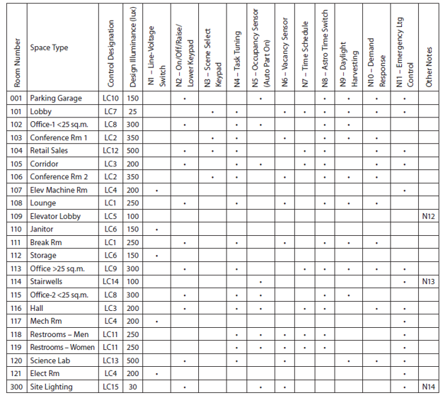
THE SOO MATRIX
The SOO contains much more specific information than the CIN and therefore more detailed organization. ANSI/IES LP-16 identifies a matrix as a suitable tool for its expression.
Vertically, we see a list of spaces or space types cast against a horizontal list of control strategies and components (such as emergency lighting control). Checkmarks in the resulting matrix indicate to what spaces or space types the control strategies will be applied.
This matrix is initially developed during the project’s conceptual (schematic) design phase. In the next phase (design development), the SOO matrix is refined with the inclusion of design light levels and initial settings, along with notes providing more detail about operation and hardware. During construction (construction documents phase and installation and programming phase), all sequences and settings are clarified, reflecting any design changes.
By the project’s conclusion, the SOO is tied to lighting control designations with detailed text sequences, notes, and room numbers on the plans. Below is our lobby example expressed in a matrix format:

And below is a more complex example of an SOO matrix refined for pre-installation and programming for an office building, courtesy of the Illuminating Engineering Society:

MOVING ON
Now you’re ready to proceed to Part 2, covering device selection and specification.