Thomas Hartman, P.E., The Hartman Company
AutomatedBuildings.com
|
[an error occurred while processing this directive] |

Thomas Hartman, P.E., The Hartman
Company
In many large
cooling systems, the chilled water distribution system
poses a much more immediate problem to overall cooling system performance and
efficiency.
Last month I outlined an approach designers and facility managers can use to evaluate the cost effectiveness of incorporating new "all-variable speed" technologies into new or existing chiller plants. All-variable speed technologies offer substantial energy use reductions and also extend the life of the plant's chillers while lowering their maintenance requirements. However, in many large cooling systems, the chilled water distribution system poses a much more immediate problem to overall cooling system performance and efficiency. Because many chilled water systems fail to attain their design delta T, loads at the end of the distribution system may be starved at peak periods, while at the same time the chiller plant is not able to utilize its full design capacity. Many "fixes" worsen the problem by raising the chilled water supply temperature to loads which reduce their latent cooling capacity and result in an endless stream of complaints. At some facilities, the inability to solve nagging distribution problems has undermined the integrity of the entire central plant and new approaches for cooling are being considered by unhappy end users.
|
Tom's May article - the third in the series: Optimizing All-Variable Speed Systems with Demand Based Control Tom's March article - the first in the series: All-Variable
Speed Chilled Water Distribution Systems: Optimizing Distribution Efficiency |
Truly effective solutions to such problems are relatively straightforward, and extending all-variable speed principles to the chilled water distribution system facilitates such solutions. So this month, I will expand the discussion started last month and outline how all-variable speed technologies can be most effectively extended to upgrade chilled water distribution systems for better performance.
Distribution System Problems
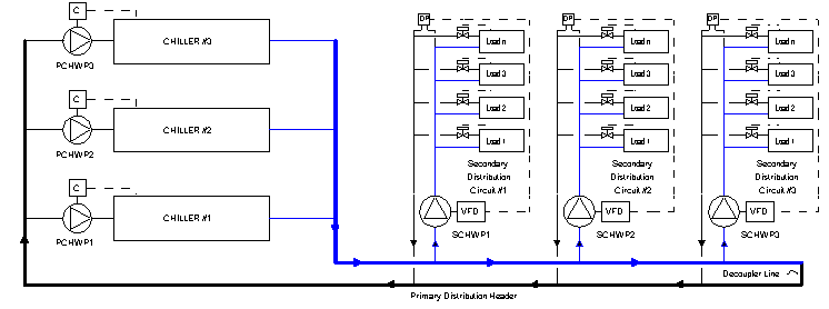
Though chilled water distribution systems vary enormously in size and configuration, the problems associated with these systems are quite universal: low delta T, inability to fully load chillers, inadequate flow in sections of the distribution system, and excessive pumping pressure requirements at peak cooling demand conditions. Some of these problems plague nearly all chilled water distribution systems. Figure 1 shows a typical primary-secondary variable flow distribution system. In smaller systems the primary loop and the secondary distribution pumps may all be located in the plant. In a large building complex, the primary (or a secondary) loop may extend throughout the campus and secondary (or tertiary) distribution pumps are typically located in the individual buildings served by the distribution system. Actual configurations may have more or less distribution circuits and usually will have multiple pumps at each pumping station. However, the lessons discussed here are generally scalable and are easy to apply to a wide variety of distribution systems.

Figure 1: Typical Chilled Water Distribution System Configuration.
In Figure 1, the primary chilled water pumps (PCHWP1 - 3) are nearly always constant speed pumps and the secondary chilled water pumps (SCHWP1 - 3) are variable speed pumps. The primary pumps are cycled on and off with the chiller each serves, and the speed of the secondary pumps is modulated to meet a differential pressure setpoint as measured at the end of the distribution circuit each serves. A decoupling line shown in the lower right end of the figure permits flow in either direction at the end of the primary circuit since the "stepped" primary flow will nearly always be different than the continuously variable secondary flow. This system is widely employed, but has two inherent problems that lead to low delta T and poor performance:
|
|
|
|
|
|
|
|
|
|
|
|
|
|
|
[an error occurred while processing this directive] |
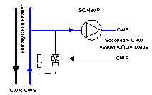
Because primary and secondary flow is almost never exactly balanced and actual delta T always varies somewhat from design, one of the two problems is almost always at play in such systems, both of which can reduce the design delta T of the system and both of which make it difficult to operate the system effectively at full capacity. A number of solutions have been proposed to correct this problem, but such "cures" often destroy the system's ability to meet the cooling load requirements. One popular method of correcting low secondary circuit delta T problems is shown in Figure 2.

Figure 2: Diagram of a Typical Delta T "Enhancement"
While the Figure 2 diagram, or some variation of it, is often touted as a cure for low delta T, it much more often has disastrous effects on system operation. The idea is that the diverting valve on each secondary (or tertiary in some cases) circuit return (sometimes a mixing valve is used on the chilled water supply) will modulate some return water back to the pump anytime the return temperature is below design. It is reasoned that the elevated supply temperature will raise the return temperature and ensure that the design delta T from the circuit is maintained at all times. However, this fix rarely has the desired results. When air is the medium being cooled, return chilled water temperature is much more affected by entering air temperature than chilled water supply temperature. Raising the chilled water supply temperature thus has little effect on return chilled water temperature, but it does profoundly reduce cooling coil capacity, especially latent cooling capacity. As the supply chilled water temperature rises, load valves open further and flow in the circuit increases dramatically, often without a significant increase in the return water temperature and usually with a reduction in cooling effect. Thus, when the scheme shown in Figure 2 is installed on a distribution circuit, one poorly operating load in the circuit can severely compromise the capacity of all loads in the circuit. In large systems it is also possible at times to have the flow reversal such that return chilled water from the mains travels to the supply header through the diverting or mixing valve. Thus the Figure 2 "fix", and the many schemes that are similar to it, do not fix system operation at all. Instead, it is a "poison pill" to chilled water distribution systems.
Getting Real About Low Delta T
[an error occurred while processing this directive]So what is the solution to low delta T problems? To configure a successful solution we must recognize what helps and hinders delta T. Delta T problems are sometimes caused by the designs themselves which may include added bypasses and three way valves scattered through the system to keep water moving at low load conditions. Solutions that involve mixing return water with supply water undermine the thermodynamic efficiency of the system, destroy the capacity of the coils to meet their loads, and add further to low delta T problems. To solve the types of distribution problems that lead to low delta T, the design or retrofit needs to follow these rules:
Configuring The Solution
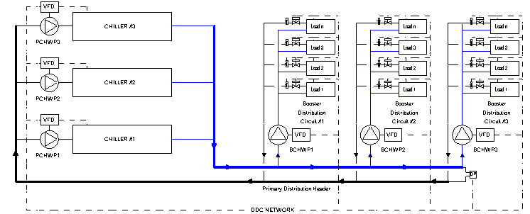
Figure 3 shows a system incorporating the above points that ensures every load will be satisfied and guarantees that the design delta T is maintained at all times.

Figure 3: "All-Variable Speed" Chilled Water Distribution System Configuration with Network Controls
Notice how similar Figure 3 is to Figure 1. Because there are no decoupling lines in Figure 3, it is called an "all-variable speed series Primary/Booster system." Here are how the rules listed above have been implemented to convert the conventional Primary/Secondary system to a Primary/Booster and solve the problems typically associated with distribution systems:
Other Design Considerations
There are some hydronic issues that must be addressed with large series pumping systems. The potential for water hammer is increased because without decoupling lines, flow through the entire system will change if a rapid change of flow occurs through any large load. However, simple steps will ensure that water hammer will not be a problem. First, the all-variable speed distribution system shown in Figure 3 should employ electrically actuated modulating valves. Large valves usually employ 90 second to 360 second motors. This means that the valve cannot abruptly change flow to cause water hammer. If other considerations make water hammer still a possibility, the potential can be further mitigated by using distributed expansion tanks. With this, a small expansion tank can be installed at each booster pumping station. When correctly piped, in addition to providing temperature expansion protection for each booster circuit, the distributed expansion tanks will act as buffers to absorb potential pressure spikes between the booster circuit and the remainder of the system.
[an error occurred while processing this directive]Another potential issue with the configuration shown in Figure 3 is the need to ensure some level of minimum flow anytime a chiller is operating. Without any decoupling or bypass, the flow will drop to zero if all the valves close. The simplest solution is to shut the last remaining on-line chiller down when the flow falls below a predefined minimum threshold. Consider that in many comfort cooling applications, this low flow condition will be reached when the outside temperature is very close to the point at which outside air economizers alone can provide the supply air temperature setpoint. By shutting down the mechanical cooling, the supply temperature may rise slightly, requiring some additional fan power to meet the cooling load, but the overall system may still operate much more efficiently than by keeping a nearly unloaded chiller on line.
If chiller operation at low loads is necessary, then it is a simple matter to add a small bypass valve in the primary circuit that is normally closed but opens at low flow conditions to maintain a minimum flow rate.
Evaluation Costs and Savings for an All-Variable Speed Upgrade
While the savings that can be expected from upgrading an existing decoupled primary - secondary distribution system to an all-variable speed primary - booster system may not be eye catching, the costs for such an upgrade are also often quite modest. Adding variable speed drives to the constant speed primary pumps, closing bypasses and implementing new network control can be accomplished quite economically in many systems. So, even though the energy economics may not be enormously attractive at first blush, the potential benefits to the overall cooling system are. The main driving forces for retrofitting to an all-variable speed distribution system are:
These are big problems for some facilities, and converting to an all-variable speed primary/booster chilled water distribution system can usually lead to enormous improvements at relative low costs. However, such a conversion needs to be very carefully analyzed and designed to be sure the retrofit does not introduce new hydraulic problems into the system and that the chillers and other plant equipment maintain adequate minimum chilled water flow at all times. Cost is not generally a major consideration for a primary/booster upgrade, but a careful design process should be!
Summary & Conclusion
Low delta T problems are very widely experienced by chilled water distribution systems in operation today. Many of the fixes that have been suggested to mitigate low delta T offer no solution at all, only more problems. However, reconfiguring such chilled water distribution systems as primary/booster "all-variable speed" systems without decoupling lines and with return chilled water temperature limits on each load will absolutely guarantee an end to low delta T problems. Furthermore, such a system can alert operators to potential problems at loads that are under performing so that these problems can be corrected before they adversely affect the comfort of the spaces served. With a carefully developed design, an economical upgrade is often achievable that will greatly improve overall cooling system performance.
Additional information on technologies discussed in this article is available at www.hartmanco.com. Comments and questions may be addressed to Mr. Hartman at tomh@hartmanco.com.
References
1. The
Hartman Company, 2001, "The Hartman LOOP Chiller Plant Design and
Operating Technologies: Frequently Asked Questions," March
2.
Hartman, T, 2001, "Getting Real About Low Delta T in Variable-Flow
Distribution Systems," HPAC Engineering April.
3. Hartman, T., 1996, "Design
Issues of Variable Chilled Water Flow-Through Chillers," ASHRAE
Transactions, June.
4. Hartman, T.B. 1999, "Network
Based Control of Fluid Distribution Systems," Renewable And Advanced
Energy Systems For the 21st Century, Lahaina, Hawaii.
5. Kirsner, W., 1996, "The
Demise of the Primary-Secondary Pumping Paradigm for Chilled Water Plant Design,"
Heating/Piping/Air Conditioning (HPAC) November.
[an error occurred while processing this directive]
[Click Banner To Learn More]
[Home Page] [The Automator] [About] [Subscribe ] [Contact Us]