|
|
David S. Dougan, President |
AutomatedBuildings.com
|
[an error occurred while processing this directive] |
|
|
David S. Dougan, President |
INTRODUCTION

The proper selection of airflow measurement devices can be critical to the performance of today’s state-of-the-art HVAC system. Many of the requirements and limitations of one technology are often mistakenly thought to apply to every other. Not all technologies result in equal performance, even when used under similar conditions. Accuracy and repeatability vary between technologies and are most dramatically influenced by installation location, airflow rates, and required system turndown.
The two most common airflow measurement technologies commonly used in HVAC systems are (1) totally electronic thermal dispersion and (2) differential pressure based Pitot arrays. This article will relate both theoretical and laboratory test results of a scientific study performed by the author over the past 2 years. Designers should understand the advantages and limitations of each technology prior to selecting a device for a specific application.
|
[an error occurred while processing this directive] |
A BRIEF HISTORY OF AIRFLOW MEASUREMENT FOR HVAC
During the period when pneumatic controls dominated the industry, differential pressure based airflow measurement was the logical choice for HVAC applications. The Pitot-static tube could transmit the square root velocity equivalent of a single point, the velocity pressure, directly to the host control system.
When VAV systems began to dominate designs, there became a significant need to measure airflow rates for volumetric fan tracking. Enterprising individuals recognized the limitations of single point measurement and developed the averaging Pitot array. Although the device introduced a sampling error from averaging a nonlinear pressure signal, the technology was sufficient to meet the requirements of early VAV systems.
Direct digital control (DDC) systems began to replace traditional pneumatic systems in the early 1980’s. Airflow measurement required an additional "transducer" to convert the pneumatic signal to an electronic equivalent for the DDC system. Because the differential velocity pressure was very small, the error of the conversion was significant and is still today a significant source of uncertainty when using Pitot array technology.
Airflow measuring devices used in traditional HVAC systems were designed for basic balancing and thermal comfort. Maximum airflow rates of 2,500 fpm typified most systems. A working turndown of 3 to 1, or a minimum velocity of approximately 800 fpm, was accepted as the minimum airflow rate that measurement devices needed to operate satisfactorily. In addition, a minimum "straight run" of 10 duct diameters was required for "acceptable" measurement accuracy. In many cases, a flow-straightening honeycomb was required to minimize the averaging error of the manifold.
As HVAC system technology increased, so did the requirement for more accurate and stable airflow measuring devices. During the 1980’s new technologies entered the airflow measurement arena. One technology utilized the principle of thermal dispersion. The new technology provided the host control system with a single, linear signal for airflow using an array of independent sensors without using additional transducers. In addition, thermal dispersion devices could accurately measure airflow rates down to still air (although the practical application of such measurement is rarely encountered). The thermal dispersion device also could provide the host control system with a signal for average temperature.
UNDERSTANDING THE DIFFERENCES BETWEEN THE TECHNOLOGIES
Comparing technologies that are vastly different is not a simple task. Besides the principle of measurement (thermal or differential pressure), there are a number of subtle factors that have a dramatic effect on overall performance. The primary factors are listed below and will be evaluated in subsequent sections of this article.
Influence of up and down stream disturbances:
Effect on individual sensor accuracy (effect of "turbulence")
Effect on overall sampling error of the array (effect of the velocity profile)
Calibrated accuracy of the sensor(s)
Calibrated accuracy of the transmitter/transducer
Effect of placement of the sensor probe with respect to the velocity vector plane (rotation effect)
Long-term stability
[an error occurred while processing this directive]INFLUENCE OF UPSTREAM AND DOWNSTREAM DISTURBANCES
Duct fittings and accessories, including elbows, transitions, fans, dampers, and plenums will create excessive duct eddies ("turbulence") and velocity profiles that will add to the uncertainty of measurement for airflow measuring devices. Thermal dispersion devices are influenced by these disturbances differently than differential pressure based devices. Ebtron, Inc., a manufacturer of thermal dispersion airflow measuring devices conducted extensive testing over a period of more than one year to evaluate the effect of up and downstream disturbances on both thermal dispersion devices and differential pressure based Pitot tubes and arrays.
Effect on Individual Sensor Accuracy (effects of "turbulence")
Thermal Dispersion Devices
The scope of this article will be limited to the thermal dispersion measurement technology developed by Ebtron. A subsequent project could compare various thermal technologies.
Early (prior to 1993) thermal dispersion arrays were significantly influenced by duct turbulence. Airflow measuring stations placed in locations close to duct disturbances often exhibited a "false high" reading. Since the technology determines airflow by relating the heat transfer rate from a warm body to the velocity, duct locations having excessive eddies and turbulence removed more heat from the sensor than it was exposed to under factory wind-tunnel calibration, hence, the high reading.
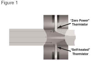 Enhancements
to Ebtron’s sensor design in the early 1990’s placed the heated sensor in
the turbulent wake created by the sharp leading edge of the sensor probe
assembly (figure 1). This "preconditioning" effect essentially made
all of the airflow across the sensor more "turbulent" than the
worst-case disturbance effect, therefore allowing for the condition to be
created and used during the calibration process. As a result, Ebtron thermal
dispersion sensors are influenced less by duct disturbances than any other
technology, based on laboratory testing. Often, less than 1 equivalent diameter
is adequate for accurate measurement when high sensor density devices are
applied. These statements will be supported in research data presented later in
this article.
Enhancements
to Ebtron’s sensor design in the early 1990’s placed the heated sensor in
the turbulent wake created by the sharp leading edge of the sensor probe
assembly (figure 1). This "preconditioning" effect essentially made
all of the airflow across the sensor more "turbulent" than the
worst-case disturbance effect, therefore allowing for the condition to be
created and used during the calibration process. As a result, Ebtron thermal
dispersion sensors are influenced less by duct disturbances than any other
technology, based on laboratory testing. Often, less than 1 equivalent diameter
is adequate for accurate measurement when high sensor density devices are
applied. These statements will be supported in research data presented later in
this article.
Pitot Tubes and Arrays
 Both
laboratory Pitots and averaging Pitot arrays are influenced by turbulence in a
similar manner. The velocity, V, is expressed as
Both
laboratory Pitots and averaging Pitot arrays are influenced by turbulence in a
similar manner. The velocity, V, is expressed as
(equation 1)
V=(2DP/p)0.5
where DP (DeltaP) is the differential pressure, and p is the density of the air.
The differential pressure is small compared to the total pressure of the air stream in most HVAC environments. The resulting signal-to-noise ratio is significant when sampling small fluctuations in total pressure of the air stream (figure 2). For example, a duct having a total pressure of 2.0 in.H2O and a pressure fluctuation of ±1% will experience fluctuating "noise" of ±0.02 in.H2O. The velocity pressure associated with 1,000 fpm is equal to 0.062 in.H2O. In this case the "noise" is nearly 1/3 of the total signal. The effect is amplified when Pitot instruments are placed closer to disturbances and at lower airflow rates. As a result, it is not uncommon for air balance professionals using differential pressure based devices to indicate negative or "unreliable" airflow rates near elbows, on the inside portion of the duct where the airflow is lowest. Newer hand-held devices actually force unreliable readings to 0 fpm, which can add to field measurement uncertainty when traversing in less than optimal duct locations.
Ebtron testing has indicated that in many cases, there was still a net positive airflow present when differential pressure based devices indicated negative or unreliable flow rates (see Placement Test Summary). As a result, and in order to achieve maximum potential performance, differential pressure devices should only be applied when the circumstances allow placement in greater than approximately 10 equivalent duct diameters of straight duct (7.5 duct diameters downstream and 3 upstream).1,4,5
Effect on the Overall Sampling Error of the Array (effect of the velocity profile)
Both thermal dispersion and Pitot arrays determine the average velocity for conversion to a volumetric rate by sampling the velocity profile. Thermal dispersion measures velocity directly, while Pitot arrays sample the distribution of total and static pressures that represent velocity.
How many sampling points are required for accurate measurement and what should the sensor distribution be? Will x number of sensing points in a thermal dispersion device yield the same performance as x number of sampling points on a Pitot array?
International Standard ISO 3966, Measurement of fluid flow in closed conduits - Velocity area method using Pitot static tubes (1977)3, defines the currently accepted method for traversing ducts. The standard assumes the existence of a specific velocity profile function and recommends a specific number of measurements and the location of such measurements within the duct using the "Log-Tchebycheff" method. According to the Standard: "By hypothesis the mathematical form of the velocity distribution law as a function of the distance from the wall is logarithmic in the outermost elements of the section and polynomial in the other elements." The Standard recommends a minimum of 25 points be measured in rectangular ducts. The ISO Standard has also been adopted as the basis of ANSI/ASHRAE Standard 1111.
A number of authors have commented on ISO 3966 and the use of the "Log-Tchebycheff" method. Ebtron offers airflow devices with sensor distribution based on either the "Equal Area" method or "Log-Tchebycheff" method. However, testing has been inconclusive as to the best choice for most HVAC environments, since "Log-T" distribution makes assumptions that do not necessarily characterize the flow profiles of many HVAC duct systems, which have numerous fittings and disturbances.
It is critical to recognize that the ISO Standard is based solely on the use of Pitot static tubes. Uncertainty analysis presented in the Standard clearly indicates that a number of systematic and random errors are associated with the technique. "Errors in the estimation of local velocity" include those contributed by the velocity fluctuations during the traverse, turbulence and error due to the inclination of the Pitot tube. "Errors in the estimation of flow rate" add uncertainty contributed by the positioning of the Pitot tube. All of these factors are unique to hand-held Pitot tube traverses. As a result, sampling theory dictates that a larger number of sampling points will result in a better estimation of the true average and minimize experimental error. The number of sampling points recommended by this method cannot be transferred to permanently mounted duct devices which do not have all of the inherent systematic and random errors associated with field measurement.
ASTM Standard D 3464-75, "Standard Test Method for Average Velocity in a duct using a Thermal Anemometer" , specifies 4 to 20 sampling points, depending on the size of the duct. 2
Tests conducted at the U.S. Army Corps of Engineers’ Construction Engineering Research Laboratory (UACERL) evaluating sensor density of traverses and various airflow measuring devices, concluded that low sensor density probes (3 sensors in a 22" x 40" duct) resulted in the same accuracy as a 35 point traverse measurement 4.
Thermal Dispersion Devices
Ebtron determined the number of independent thermal sensors required for accurate measurement in a series of laboratory tests. Early Ebtron airflow measuring devices provided up to 4 sensors per square foot, in accordance with previous ASHRAE guidelines. That sensor density would yield an installed accuracy of ±2% of reading when installed in accordance to factory guidelines. Practical considerations suggested that a decrease in sensor density by 50% would effect an increase in error of only +1% of installed accuracy, to ±3% of reading. This would result in adequate performance for installations requiring precise measurement of airflow rates.
The following guidelines were developed from laboratory testing and field experience for precision airflow applications. The guidelines are based on duct size and covers the sensor density provided with all Ebtron model GTx116-PC airflow measurement systems.
Performance under a variety of duct locations can be found in the Placement Test Summary section of this document.
[an error occurred while processing this directive]In many cases, such as with fan tracking applications, repeatability, linearity and turndown are more important than installed accuracy. Reduced sensor density devices are available at a lower price. For applications requiring an installed accuracy ±6% or better, the GTx116-PB will result in satisfactory performance. A more economical model STx102-P will result in an installed accuracy of ±10% or better. In most cases, these lesser sensor density devices can be adjusted in the field and result in excellent performance with the same long term stability as the precision model GTx116-PC.
Similarly, fan inlet devices (like models GTx116-F and STx104-F) provide repeatability, linearity and turndown with lesser-installed accuracy. Variability in the fan inlet, including the existence of disturbances (belt-guards, bearing housings, etc.) and inlet entry conditions (proximity of walls and partitions) generally results in an installed accuracy of ±10% and require field adjustment. For fan tracking applications, adjustments are simple and require that intake and exhaust dampers are closed with the recirculation damper in the full open position. Either one station or readings from an air balance contractor are used as a reference and a correction factor for the unit(s) to be adjusted is calculated (for details refer to Application Notes for Fan Tracking in the Ebtron Advantage Product Catalog).
Pitot Tubes and Arrays
Professional TAB contractors traverse a duct and record individual readings. Each reading is determined by evaluating the equation V=4005*(DP)0.5, where DP is measured as inches of H2O. This generalized relationship does not account for changes in air density due to changes in air temperature and pressure. The readings are added together and a final average airflow rate is determined. Taking multiple readings throughout the duct can compensate for changes in the velocity profile.
Pitot arrays, by definition, average the velocity profile before the airflow rate is determined. The arithmetic difference between individual methods can result in a significant error in airflow measurement. Manufacturers of Pitot arrays promote high sensor densities as a product feature and suggest that the sensor density of devices using independent sensors is inadequate. On the contrary, Pitot arrays are only single sensor devices (the pressure transducer) using multiple pickup points, and have far less sensor density than devices that have truly independent sensors. The differences can be easily demonstrated both theoretically (figure 3) and in laboratory testing (see: Placement Test Summary).
Placement Test Summary
Various duct configurations were setup in the Ebtron research laboratory. An Ebtron model GTx116-PC probe was used as the thermal dispersion device. The GTx116-PC was configured based on catalog recommendations of 2 probes, 3 sensors each, for a total of 6 sensing points. Averaging Pitot probes from a leading manufacturer was used in conjunction with a MKS Baratron, 0.05% of reading, industrial pressure sensor and transmitter. The Pitot array was configured as 2 probes, 7 pickup points each, for a total of 14 pickup points as recommended by the manufacturer for the duct size being evaluated. The following summary is indicative of tests conducted in the lab.
Elbow Tests
A duct system was constructed using 24" x 24" galvanized duct. 18 feet of straight duct was connected to a transition from a backward inclined centrifugal fan. At the end of the straight portion of duct, a 90-degree elbow was installed. An additional 8 feet of straight duct was connected to the elbow. A reference point was selected at a position 11 feet downstream of the transition from the fan.
The fan speed was maintained at nominal velocities of 250, 500, 1000, 1500, and 1750 fpm using a variable speed drive. Each airflow measuring device was placed at the reference position and measurements were recorded using a Fluke Helios datalogger. Without changing the speed of the fan, each airflow measuring device was positioned at a number of points upstream and downstream of the elbow. Each device was evaluated against itself, by comparison to its own reference point measurement. Composite data is used in all summary figures.
Both devices performed well when turning vanes were installed (figure A). However, there was a significant difference in performance in the absence of turning vanes (figure B). The maximum uncertainty of the thermal dispersion device was 10% while the Pitot array exceeded 50%.
A similar test was setup for return duct analysis. Since turning vanes are not routinely installed in return ducts, the test was conducted in the absence of turning vanes. Once again a similar difference in performance was measured (figure C).

The elbow test clearly demonstrates that the thermal dispersion probe with 6 independent sensors outperformed the averaging Pitot array with 14 pickup points close to the elbow. Most of the error of the Pitot array can be explained by the mathematical inequality shown in figure 3.
Another test was run downstream of the transition from the fan. Data is summarized in figure D.
Although locations could have been selected where the Pitot array performed well, it is critical to recognize that this test was based on a single disturbance only. Actual HVAC environments have considerably more variable conditions. As a result, designers should select an airflow measuring device that can perform under difficult conditions. Minimum placement requirements cannot always be achieved in "real-world" systems and installing contractors do not always place devices where designers intended.
An additional test was conducted to determine the performance characteristics of both devices near an intake damper. Each device was installed upstream of an opposed blade damper. The damper was connected to a plenum, which was connected to a laboratory wind tunnel. The damper was positioned at 100%, 75%, 50%, and 25% of stroke to determine "damper interaction". The results are shown in figure E and demonstrates that the thermal dispersion device was not influenced by the velocity profile upstream of the damper. The Pitot array was unable to produce reliable measurements.
CALIBRATED ACCURACY OF THE SENSOR(S)
Thermal Dispersion Devices
Each Ebtron thermal dispersion sensor is comprised of two hermetically sealed "bead-in-glass" thermistor probes. One thermistor probe measures the ambient air temperature and the other is "self-heated" and measures the power dissipated to the air stream. Resistance/temperature data is carefully collected in precision constant temperature baths and automatically tracked with serialized identification. The two thermistor probes are mounted in a housing to make an individual "sensor". Each "sensor" is calibrated in a wind tunnel at 15 velocities, starting from still air, between 0 and 5,000 fpm for probe sensors (0 and 10,000 fpm for fan inlet sensors). The calibration reference standard used by the wind tunnel is sent to the National Institute of Standards and Technology (NIST), where it undergoes tests in the facility’s low speed (Laser-Doppler) and high-speed wind tunnels. The uncertainty of the calibration is better than ±2% of reading.
Pitot Arrays
Pitot arrays rely on the physical relationship between differential pressure and velocity. Their calibration factor, K, is generally assumed to be unity (1). However, in practice, the calibration factor is rarely equal to 1. The factor is variable, and a function of the Reynolds number, Re, which is expressed as
Re = Vd/v
where V is the velocity, d is the diameter of the Pitot tube, and v is the kinematic viscosity.
Therefore, using a single calibration factor (common for commercial HVAC devices) will result in error in measurement as the airflow rate varies. They are normally "calibrated" in the field and referenced to a duct traverse with hand-held instruments or some other secondary source.
Nonetheless, Pitot tube arrays can demonstrate accuracies of ±2% (not including the pressure transducer error rates), when compared to laboratory test tunnels having very "flat" velocity profiles with sufficiently high Reynolds numbers (i.e. V > 600 fpm). The Associated Air Balance Council (AABC) in their 2002 Standards requires minimum average traverse velocities of not less than 1,000 fpm. 6
CALIBRATED ACCURACY OF THE TRANSMITTER OR TRANSDUCER
The published sensor accuracy of the Ebtron thermal dispersion device to the host controls includes the error of the transmitter. Because the accuracy of the differential pressure output of the Pitot arrays is stated separately from the pressure transducer, the combined accuracy of the two devices is often misinterpreted. In most cases, the pressure transducer is the greatest source of error when using Pitot tubes and arrays. Understanding transmitter and transducer error is critical when selecting an airflow-measuring device for an application.
Thermal Dispersion Devices
All Ebtron transmitters use state-of-the-art microprocessor based technology. Voltages from individual sensors are multiplexed and converted to binary with precision analog-to-digital (A/D) converters. The binary signals are then processed through a proprietary algorithm to calculate the airflow rate and temperature of each sensor using precision floating-point math routines. Individual airflow rates (and temperatures) are averaged for a final output to the host controls. A typical sensor will exhibit a 1.5 volt change between 0 and 400 fpm. The electronics can resolve that voltage to approximately 0.002 volts. As a result, transmitter error is negligible. Ebtron devices are "percent of reading" throughout the entire calibrated range. Neither the maximum or minimum airflow rates affect the selection and performance of the device.
 Pitot
Arrays
Pitot
Arrays
The accuracy (and cost) of pressure transducers varies widely. All pressure transducers used for commercial HVAC applications have their accuracy stated as a "percent of natural span". Therefore, a pressure transducer with a span of 0 to 1 in.H2O with an accuracy of 1%, will have an uncertainty of 0.01 in.H2O throughout the entire range of the sensor. Because the relationship of airflow to differential pressure is a square root function, the uncertainty of the pressure transducer results in significant and increasingly greater "percent of reading" errors as the airflow rate is turned down (figure 4).
The maximum uncertainty for pressure transducers having published accuracies of 1%, 0.5%, 0.25%, and 0.1% are indicated in tables 1, 2, 3, and 4 respectively (see below conclusions). When reviewing the tables, recognize that the "natural span" of a pressure transducer cannot be changed and the "usable" full scale of the device should be selected at no greater than 90% of the natural span. For example, an application having a maximum velocity of 2,000 fpm should select a pressure transducer with a natural span of 0 to 0.5 in.H2O. If the minimum velocity to be measured was 500 fpm, the potential error from the transducer and a 2% of reading Pitot tube would be 18% with a 1% transducer, 10% with a 0.5% transducer, 6% with a 0.25% transducer and 3.6% with a 0.1% transducer. Remember, these uncertainties do not include the errors of an averaging Pitot array that may result from velocity profiles. Many return ducts (and fan inlets) have significant airflow turndown ratios since the outside airflow rate is generally a constant volume. In addition, outside air intakes with an airside economizer can also experience significant turndown if a separate, minimum outside air damper is not installed. Therefore, great care should be given to the selection and application of Pitot arrays and transducers.
High performance, "percent of reading" industrial pressure transducers are available but their cost (usually in excess of $5,000) makes their application in HVAC control not practical.
 EFFECT
OF PLACEMENT OF THE SENSOR PROBE WITH RESPECT TO THE VELOCITY VECTOR PLANE
EFFECT
OF PLACEMENT OF THE SENSOR PROBE WITH RESPECT TO THE VELOCITY VECTOR PLANE
(ROTATION EFFECT)
Whether or not an airflow measuring device is influenced by rotation, with respect to the velocity vector plane, depends on the installing contractor’s ability to properly install the device. Wind tunnel tests evaluated thermal dispersion probes and averaging Pitot probes. Each probe used its properly aligned position for an initial reference measurement. Measurements were taken at 5° increments between 0° (reference position) and 30 °. The results are shown in figure 5.
CONCLUSIONS
Designers must understand the true "apples to apples" comparison when selecting airflow measuring devices that utilize different technologies.
Thermal dispersion devices have been designed to measure accurately under turbulent conditions created by upstream and downstream duct disturbances. Differential pressure based Pitot tubes and arrays require longer straight duct runs than the thermal dispersion devices tested as a result of a smaller signal-to-noise ratio.
Disturbances have a dramatic effect on the duct velocity profile. The velocity profile requires that multiple points be measured to produce an accurate airflow rate. Permanently mounted devices have fewer systematic and random errors than field measurement and can produce more reliable measurement with fewer sampling points. Thermal dispersion devices independently determine the airflow rate at each measurement point prior to averaging. Pitot arrays average nonlinear velocity pressure signals from multiple pickup points. Averaging errors exceed those of devices using independent sensors, even when the number of pickup points far exceeds that of the independent sensing device.
Each Ebtron thermal dispersion sensor is wind tunnel calibrated at 15 points against reference standards that are regularly verified by NIST. Pitot arrays use a single flow coefficient and assume that the calibration factor is unity throughout the entire airflow range.
Ebtron thermal dispersion transmitters use high accuracy A/D converters to measure sensor voltages. All algorithms are processed using floating-point math routines. As a result, the transmitter adds negligible error to the measurement. Pitot array performance is significantly influenced by the accuracy of the pressure transducer, which is typically a "percent of full scale". The square root relationship between velocity and velocity pressure requires extreme caution by the designer when selecting pressure transducer accuracy and span. Useable turndown is limited by the transducer accuracy.
Ebtron thermal dispersion probes can withstand greater rotation in the duct than Pitot arrays, although both devices should be installed with the sensors or pickups oriented as close to parallel to the airflow vector plane as possible.
Over the past several decades, the requirement for HVAC airflow measurement has changed. Pitot arrays have dominated the industry since their inception and have influenced the perception of the engineering community about the limitations and reliability of all airflow measurement instruments. Ebtron’s thermal dispersion devices provide design engineers with a versatile option that can be economically competitive with Pitot array systems.
References
1 ASHRAE. 2001. Handbook of Fundamentals. Chapter 14. "Measurement and Instruments". American Society of Heating, Refrigerating, and Air-Conditioning Engineers, Inc. Atlanta, GA
2 ASTM. 1984. Standard D 3464-75. "Test method for average velocity in a duct using a thermal anemometer". American Society for Testing and Materials International, Inc. West Conshohocken, PA
3 ISO. 1977. Standard 3966. "Measurement of fluid flow in closed conduits - Velocity area method using Pitot static tubes". International Organization for Standardization, Geneva, Switzerland.
4 Schwenk, David M. 1998. Air Flow Measurement Accuracy. Heartland Technology Transfer & Training Conference at Kansas City MO. Sponsored by Headquarters, U.S. Army Corps of Engineers, Construction Engineering Research Laboratories (USACERL). Champaign, IL (http://www.hq.usace.army.mil/cemp/e/Et/flow.pdf)
5 ANSI/ASHRAE. Standard 111-1988. "Practices for Measurement, Testing, Adjusting, and Balancing of Building Heating, Ventilation, Air-Conditioning, and Refrigeration Systems". American Society of Heating, Refrigerating, and Air-Conditioning Engineers, Inc. Atlanta, GA
6 AABC. 2002. National Standards for Total System Balance. Chapter 3 – Airside Volume Measurement. Associated Air Balance Council, Washington, D.C.
[an error occurred while processing this directive]
[Click Banner To Learn More]
[Home Page] [The Automator] [About] [Subscribe ] [Contact Us]