May 2009
![]()
AutomatedBuildings.com
[an error occurred while processing this directive]
(Click Message to Learn More)
May 2009 |
[an error occurred while processing this directive] |
|
Points List Primer A “pointed” view of
hardwired I/O |
|
To begin this column on points, I offer the definition of the term as it’s presented in the glossary of my book, Practical Controls: A Guide to Mechanical Systems:
|
|
|
|
|
|
|
|
|
|
|
|
|
[an error occurred while processing this directive] |
|
|
|
|
|
|
|
|
|
|
|
|
|
|
|
[an error occurred while processing this directive] |
Points (Points of Control) – A term used to
describe a control operation, whether it be a sensing action or a controlling
action. A point can be anything from a temperature sensor, to an output of a
proportional controller operating a control valve. With digital controllers, a
tally of the used inputs and outputs can provide an overall “point count” of a
control system, and in this respect can serve as a quantitative evaluation of
the given system.
In the world of Building Automation, we’re typically dealing with distributed
digital control, meaning that there are digital controllers spread throughout a
given facility, with each controller operating a unique mechanical system,
subsystem, or piece of equipment, with all of the controllers tied together via
the network communication cabling. The control system is distributed in the
sense that there is not one single controller that all input/output points tie
into, but many controllers. The control logic of the entire system is
distributed among the networked controllers, and each controller has its own set
of inputs and outputs, to monitor real world variables (i.e. space temperature)
and control real world devices (i.e. outside air damper).
In this article we consider those points that are indeed “hardwired” into a
digital controller, as the definition above alludes to. There are other
variables or pieces of information that are referred to as points, digitally
speaking, that won’t be covered here, such as virtual (internal) points and
BACnet (network) points, to name a few. To focus on the topic at hand, we
restrict our discussion to hard points, those that are typically included on
points lists.
A points list simply specifies the input and output points that are required for
a project. Specifying points is a great method for getting what is needed on a
DDC project. The idea is to account for all of the points up front and get them
into the design. Points lists are typically found in the temperature controls
section of the consulting engineer’s specification, along with the Sequence of
Operation. The Sequence of Operation and the points list together are very
powerful tools for specifying a DDC control system, so long as these documents
are well-written, accurate, and inclusive of all facets of the specified
systems.
Okay, let’s get to it. As mentioned earlier, a typical networked DDC project
will consist of a network of configurable controllers, with each controller
programmed to operate a system, subsystem, or even a single piece of equipment.
For each controller, there will be its accompanying point list, which simply
details the inputs and outputs tied into that particular controller. With larger
systems, such as a boiler/chiller plant, the points list can be extensive,
whereas with unitary equipment such as single-zone rooftop units and VAV boxes,
the points list is relatively small. We’ll start by discussing the points list
for a rather large air handling unit, and work our way down to the zone level.
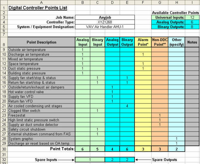
So by way of example, please consider the points list below. The first column on
the left is the Point Description, and to the right of that are the various
columns that help to describe the type of point and any additional functions
that the point may have. The first two columns are for input points. As you can
see, the first several points listed are temperature sensors, and thus are
analog inputs. Moving down the list, we then see a couple of binary or two-state
input points, for the supply and return fan “status”, which would either be a
proof-of-flow device such as an airflow or fan differential pressure switch, or
a current sensing switch, monitoring the electrical current to the motor. It’s
relevant to note that these days many (most?) digital controllers on the market,
at least those that would be considered “equipment level” controllers, have what
are referred to as “Universal Inputs”, which are inputs that can be configured
as either analog, to accept a signal as from a temperature sensor, or binary, to
accept a contact closure as from a current sensing switch. Makes for a more
flexible controller, wouldn’t you say?

Moving across the list, we encounter the columns for the output points. The
binary outputs we first see are those for the start/stop control of the supply
and return fans. These outputs would typically control relays whose contacts
would tie in to the fan starters, or in this case, the fan variable frequency
drive (VFD) run-command terminals. The analog outputs listed are for control of
the various proportional end-devices, i.e., dampers, valves, and speed-control
terminals of the VFDs.
[an error occurred while processing this directive]
A few extra columns are shown in this particular points list. If the point is to
generate an alarm, then it can be indicated here in the Alarm Point column. And
if the point is not physically tied in to the controller but is a part of the
system, it can be indicated here in the Non-DDC Point column. This may be used
to account for safety devices such as freezestats and high limit static pressure
switches, which may not physically tie in to an individual input, but need to be
listed such that they are accounted for in the design and procurement of the
system.
The points list above has an entry section at the top right that is used to fill
in the number of points available for the chosen controller. This helps keep
track of how many points are being used, and how many “spares” remain. The
spares are calculated at the bottom of the sheet. Maxxing out controllers is not
always such a good idea, especially when you consider that Murphy’s Law dictates
that if you do so, you will need another input or output point down the road.
Besides, many consultants will specify a percentage of spares required per
controller. And they may even specify how many spares of each type of point.
Moving along, let’s now take a look at a points list for a unit or zone level
controller. Many networked projects will include numerous “application specific
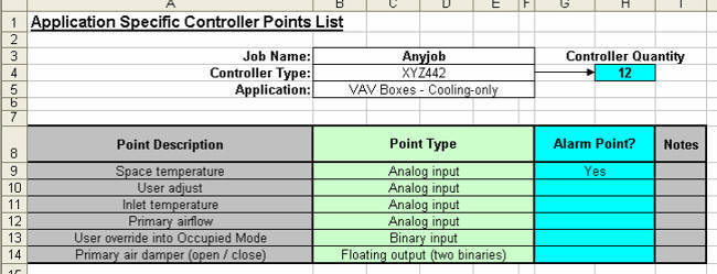
controllers” (ASCs), operating various unitary equipment. The example below
shows a points list for a cooling-only VAV box (we’ll keep it simple, as I’m
beginning to lose interest as well…just kidding, so hang on, we’re almost
done!).
As with the equipment level points list, the first column on the left is the
Point Description. The next column however is there to simply indicate the type
of point. As ASCs are generally designed to meet a specific function, whether it
be control of a packaged rooftop unit, fan-coil unit, or VAV box, the focus of
this points list is more-so on the controller itself, which isn’t to say that
the input/output devices aren’t important. On the contrary, it is extremely
important to account for all devices that need to be tied into the controller,
especially when you consider that there may be dozens and dozens of these
controllers on any given project. The point is, it’s perhaps just as important
to know the quantity of controllers (top right), as it is to know the specific
point counts of each controller.

Some final thoughts on points lists: together with the specified Sequence of Operation, points lists are an effective means of specifying a DDC project. A well-organized points list will give upwards of 90 percent of what is required for the project, control-wise. Having a points list does not, however, exempt you from reading through the Sequence of Operation, for the Sequence may include miscellaneous additional items, such as safety and limit devices. Items that, as shown in the first example, probably should be in the points list, but sometimes aren’t. Point is, you need to look at both documents, for the purpose of bidding a job and designing it. And remember to overestimate your point count, at least for the purpose of selecting your controllers and ensuring your spares!
| Tip of the Month: If the above screenshots interest you, then I invite you to visit my website at www.pcs-engineering.com for the full version of these points lists. Of course there are other sources for standard spreadsheet style point lists, and then there’s the trusty old method of “doing it yourself”. Hopefully this primer has been helpful in “pointing” you in the right direction! |
[an error occurred while processing this directive]
[Click Banner To Learn More]
[Home Page] [The Automator] [About] [Subscribe ] [Contact Us]