|
Ing. Kees van Grieken, |
AutomatedBuildings.com
|
[an error occurred while processing this directive] |
|
Ing. Kees van Grieken, |
Internet technology has been introduced into modern building management systems (BMS) with browser control, e-mail reporting and XML data exchange being integrated into intelligent controllers. All of these technologies are based on the same system: TCP/IP. This article provides details on the technology behind this network protocol plus the building management system options provided by Internet technology.
Research studies have shown that energy can be saved by linking the various systems resident in a building. The increasing demand for user friendliness, central storage of historical data, subcontracting of management tasks, and options to combine existing systems with new ones, etc has led to equipment and system installations within buildings being linked into one large interactive system. One of the most promising network technologies in this respect is TCP/IP.
|
[an error occurred while processing this directive] |
TCP/IP, which stands for Transmission Control Protocol/Internet Protocol, is actually a group of protocols. It records how data is transmitted from sender to receiver and how network users are located (IP address). However, as TCP/IP is media independent there are no specific requirements for the connection between sender and receiver enabling Internet access via cable, company network, satellite or telephone.
TCP/IP can be used with existing network structures: networks that allow companies to communicate between its remote subsidiaries. If these networks are also utilised by the BMS, then information from various subsidiaries can easily be collated and exchanged making the distance between buildings much less important.
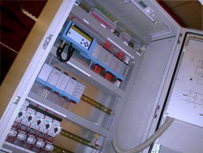
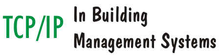
Illustration 1: Modern control computers with fully integrated Internet technology are being introduced into building management systems
By using the existing network infrastructure of the building the BMS is in a position to use available ICT (Information Communication Technology) know how and network protection features such as firewalls. This is an important safety development, particularly because of the large number of viruses that have threatened networks in the past year. Virtually all network managers are well aware of the importance of efficient network protection measures and if the BMS is only accessible via these networks then its access management protection level is automatically increased as well. An additional safety level is the need to log on to the company network.
General company
network or separate technical network?
A single network for office applications, operation of technical systems and
data exchange between equipment benefits both management and installation. There
is no requirement for routers, i.e. connection boxes, to be configured to link
networks together, communication is possible between all users and all equipment
within a building.
The disadvantages of a single network include a higher risk of misuse and a higher degree of unpredictability in network speed. Any user can access the network equipment including unskilled users or those with malicious intent. Furthermore, when transmitting large data files via the network, the average speed can drop considerably.
These disadvantages can be prevented to a large extent by segmenting the network, i.e. dividing it into individual sections. Each segment has its separate application and only information that needs to be transmitted from one segment to another is sent via routers. The best solution is variable dependent upon requirement.
Small companies usually do not have a lot of equipment connected to the network and often the tasks of a network administrator are limited. In that case it is better to opt for one network as it is easier to maintain and users will notice immediately if something goes wrong, because their PC applications will no longer operate. A separate technical network is often the best option for large companies, with only the network section between the various remotely located buildings being shared.
The future: single
network for BMS?
[an error occurred while processing this directive]The physical connection in the TCP/IP network in a building is almost always
based on Ethernet. Ethernet defines the cable needs and type of connectors.
Because of standardisation TCP/IP via Ethernet offers many advantages, however,
for the time being it will not be the only network in a BMS. Until now ICT and
BMS have been two separate entities. Project developers deliver buildings with
basic provisions, usually incorporating a BMS with associated controls, with the
network infrastructure normally installed at a later stage by the building user.
This means that the installation contractor cannot use the network for
communications between the intelligent controllers during installation. The
temporary installation of network equipment such as a hub or switch is not
without problems either as unfortunately this type of equipment is prone to
theft from building sites.
This can in part be solved by purchasing special (industrial) equipment, which is fixed in the control panel. Alternatively, good quality intelligent controllers, like the PRIVA Compri HX, provide the option of using standard twisted-pair cables for communications between the controllers. This does not require additional or separate network equipment. TCP/IP (via Ethernet) is then used to communicate between the twisted-pair controls network and workstations, and to communicate with third-party equipment.
Operation based on
Internet technology
TCP/IP can be used in two different ways for communications between the BMS and
workstations. Until now most workstations were equipped with a control
application on the PC, which retrieves and processes information from the BMS
via the TCP/IP network. The workstation application must therefore be compatible
with the BMS. The disadvantage of this set-up is that if modifications are made
to the BMS the software needs to be modified in all workstations.
The strength of Internet technology lies in the fact that information is gathered where it is produced as operation is based on the use of a browser. The browser receives information from the BMS via HTTP, the standard transfer protocol of the World Wide Web. The information is supplied ready for use so that the operator at the workstation does not need any specific BMS knowledge to display it.
To this end the BMS is equipped with a web server. The web server converts information from the installation into HTML code to be used by the browser. It is transmitted via the HTTP Internet protocol and a TCP/IP connection to the browser, such as Microsoft Internet Explorer. As the web server supplies all actual information, access is no longer required to the operator workstations should the installation change. This is particularly useful for multi-operator buildings or by remote control.
There are several reasons to opt for remote control. Firstly the distance between the installation and the workstation may be too far to allow for regular travel between the two. For example, when a service engineer needs to be able to react to a fault message from home during the evening. Secondly, when centrally managing several installations less staff are required. The third reason is that a user would not want to be tied to a specific location in order to operate the installation.
When employing remote control operation no concessions can be made to user friendliness, whereas with mobility the 'portable aspect' is important as users are not prepared to carry around a laptop all day. Fortunately Internet technology provides excellent solutions. To provide the same ease of operation with a browser as with an individual PC application on a workstation, a new display language, SVG (Scalable Vector Graphics), has been developed. Photographs, drawings, installation diagrams, etc are displayed in detail and at a surprisingly high speed.
 Illustration
2: Browser
operation and PDA enable the building management system to be controlled from
any location
Illustration
2: Browser
operation and PDA enable the building management system to be controlled from
any location
When opting for mobility the laptop with browser is not an ideal option. It is quite heavy, needs time to start up and only has a limited operating time without mains supply. The PDA, personal digital assistant or hand-held computer, is more suited to true mobility. The drawback is that it has a smaller screen and less graphic options. Furthermore, if using a mobile phone modem the communication speed will be on the low side. All the more reason to use a separate operating interface with the PDA for graphs and tables. On small screens users are better served with clear navigation structures, organised information displays and compact alarm windows.
If the controller is equipped with a built-in web server it can be accessed from anywhere in the world via a modem connection on the controller and a mobile phone connection on the PDA. The PDA can also be used in combination with a wireless LAN. When requesting parameters, commissioning or fine tuning systems, the user can read and modify the status of sensors and actuators anywhere in the building.
Integration with
Internet technology
HTML is used to send information to the browser. It describes the
information display method. It is not suitable, however, for exchanging
information between various systems, because although the value is recognised
any associated format such as degree C is not. The solution is provided by XML (eXtensible
Markup Language).
XML has been developed for data transmission with Internet technologies such as TCP/IP and HTTP. The strength of an XML based connection lies in the independence of the network used. Matters such as timing have already been handled by sub-layers (TCP/IP) so that the driver only needs to analyse and then process the information. Support for new equipment can therefore be provided at application level instead of network level, so that new connections can be established with much less effort. This increases the system integrator options considerably.
Priva: Internet ready
as standard
[an error occurred while processing this directive]
With its Compri HX range of of intelligent controllers, PRIVA Building
Intelligence is leading developments in this field having implemented TCP/IP
technology at individual controller level. An Ethernet port for rapid access to
the building's network and an embedded web server, TC WebDisplay, are delivered
as standard. The TC WebDisplay hosts web pages with information, data and
settings from the controller and from any other controllers connected on the
network. When using a PC or a PDA with a web browser these web pages can be
viewed and the settings modified. Because a standard browser is used, which is
common throughout the world, no project-dependent files are required, which
means that the building control system can be accessed anywhere and at any
time.
The Compri HX also supports wireless communications via a GSM modem. This can prove useful for a mobile or temporary installation, when a fixed telephone line is unavailable or is not allowed, as in certain industrial environments.
Conclusion
The application of Internet technology in a BMS has a number of positive
effects:
Information transfers are standardised: all equipment uses TCP/IP. This is the most commonly accepted protocol in the world, consequently more and more equipment will support Internet technology.
Distances will become irrelevant. Once the data enters the network, the distance problems are solved elsewhere: via cable, satellite or wireless. Internet technology ensures the flexibility and reliability of information transfers.
TCP/IP is media independent. This implies that optimum communication speed and cost can be selected for every application.
Internet technology defines various protocols. The transfer of information is only one aspect, a wide range of auxiliary programs (e.g. for network analysis) are available.
High security levels, with respect to both access and network reliability, are relatively simple to implement by using commercially available solutions.
Joining the technology wave. Due to economies of scale standardising software is an attractive option, this means that new options quickly become available and can be implemented just as quickly.
Internet technology is standardised and demands the same from its users. It allows improved communication and co-operation between systems. This makes TCP/IP the network technology of today and tomorrow.
Addendums:
XML
XML, which stands for eXtensible Markup Language, is a language system which
allows information to be displayed in a structured manner. It was developed in
1996 with 10 objectives in mind:
1. It should be suitable
for processing with Internet technology.
2. It should be suitable for different applications
3. It should be compatible with SGML (Standard Generalized Markup
Language)
4. It should be simple to develop programs to process XML
5. It should have as few optional features as possible
6. It should be legible and understandable
7. It should be suitable for fast design
8. It should be suitable for logical design
9. It should be possible to create an XML quickly
10. All the above objectives are more important than compactness
Because of XML information is not just transferred, but also described in a way that makes maintenance easy. The receiving party knows exactly what the information represents. In essence this implies that a temperature sensor does not just display values, such as '51.6'. It also describes them: I am a 'water temperature sensor', my location is 'Radiator office ZO', the value is '51.6', the unit is '�C' and the measurement has been recorded on '17 April 2002' at '13:47'.
This makes XML a powerful connection medium: it is suitable for transmissions across modern TCP/IP networks, it is clearly legible and easy to debug. The formal and logical notation method makes it possible to evaluate whether the data is presented correctly.
XML is, therefore, increasingly used to exchange information between two equipment items and will become an important technology in building management systems.
SVG
SVG, which stands for 'Scalable Vector Graphics', is a language used to describe two dimensional images in XML. It combines vectors such as lines and curves with (bitmap) images and text. This generates compact files. For example to describe a line the browser only needs to know the start and end points, the browser enters the line in between. It is different from the bitmap images, which are used on standard websites: they describe every dot on the line.
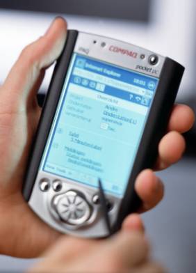
Illustration 3: Browser operation with SVG, Scalable Vector Graphics, just as user friendly as the �old fashioned� PC application.
SVG images can also be scaled. The browser can adjust the size of the image up or down to suit requirements. SVG is, therefore, eminently suitable to display system diagrams in a browser. The diagrams in visualisation programs mainly consist of lines, planes and curves. The compact description method results in short transmission times and fast operation. SVG can also display any graphic images. With a browser the user sees the same image as in a Windows visualisation program. Because the image can be scaled up or down the user never has to scroll through the image. There is no information 'outside the screen'. This is ideal when a small laptop screen and the large screen in the control room are used alternately.
SVG versus Java-applet Older Internet based visualisation programs use a Java-applet instead of SVG to visualise system diagrams in a browser. This has a number of disadvantages. Often a sizeable Java-applet has to be downloaded. This means waiting time, which does not promote user friendliness. With a Java-applet information is also much more difficult to scale: on small screens part of the information may be missing.
[an error occurred while processing this directive]A Java-applet is a type of program that runs in the browser. This makes high demands on the PC processing capacity, so that other programs on the PC are slowed down. Furthermore, Java is no longer installed in Microsoft Internet Explorer 6. A large Java-applet is not suitable for use on a PDA either.
That is why SVG is the option of the future. This technology is also recommended by the W3C (World Wide Web Consortium), which guarantees continuity and availability.
The OSI model for beginners
Every description of modern networks refers to the OSI model. This section describes an OSI model and its advantages. OSI stands for Open System Interconnection and describes the route followed by information from one application to another via a network. The basic principle behind the model is the delegation and subcontracting of tasks. Assuming that all parties are giving it their best, it does not matter how the information travels as long as it does.
To start with an example taken from the 'normal world'. Let us assume that a large machine needs to be taken to a client. One option is to take the machine in individual parts to the client by road and to reassemble them on site. The machine will get to the client eventually, but this requires knowledge of how to dismantle the machine, travel details and transport mode. Perhaps some sections cannot be transported through a tunnel. Eventually the entire machine has to be reassembled again. To facilitate matters we also assume that the entire road network is already built and available.
The dispatch can also be subcontracted to specialist transport companies. In that case the order is given to the transport company. The latter will dismantle the machine and pack it in robust crates. A logistics operator will ensure that a number of couriers are ready to transport the crates. The boxes are all labelled with an identification and sequence number. The couriers drive the crates to the client. Every courier selects the most appropriate route. Some parts are sent by road, some by train or by air. Over land, through tunnels, over bridges and by air. When the crates arrive at the client's premises they are collected and arranged in sequence. The client's logistics operator thanks the couriers for their co-operation. The parts are removed from the crates and the machine is reassembled. Mission accomplished. All that with one single command to the specialist transport company.
This may be a rather contrived example, but it is the method on which the OSI model is based. Every stage within the dispatch process is defined in a separate layer. Nearly all modern network mechanisms are based on the (partial) implementation of the 7 layer OSI model.
1. Physical layer:
transports bits, describes plugs, cables and tensions. Can be compared to the
bridge, road surface, rails in the example.
2. Data link layer: transports frames, describes the significance of the
transmitted bits. Refers to the crate, container or pallet.
3. Network layer: transports packets, describes the address and speed control.
This includes the IP part of TCP/IP. These are the couriers with their truck,
train wagon or aeroplane in the example.
4. Transport layer: transports messages, ensures reliable data transmission.
This includes the TCP part of TCP/IP. This is the distribution of the machine
between the various couriers and the verification that everything is delivered
complete and in the right sequence.
5. Session layer: opens and maintains a connection, i.e. the logistics
operator.
6. Presentation layer: makes the data suitable for transmission and vice versa.
Can be compared with the division of the machine into the parts to be
dispatched.
7. Application layer: programs such as a web server and browser. In fact, you
will notice this is where the command is given to dispatch the goods.
[an error occurred while processing this directive]Our example shows the strengths and the disadvantages of applying the OSI model. The main advantage is that, as the program increasingly uses more and more layers in the OSI model, it needs to put in less effort to make the connection. If the program remains at the application layer it only needs to issue the following command: send data to this address. The programmer need not worry about possible communication problems: they are handled by the sub layers. The disadvantage of the OSI model is that every layer means extra overheads. To return to our example: why would I dismantle the machine completely if it can be transported in one piece on a low loader?
This type of evaluation is always made during the development of network mechanisms. Do we opt for low overheads with extensive program development as a downside, or do we opt for standard network technology which need not be developed under own management, whereby we should just accept the additional overheads? Trends in recent years have favoured the latter option, with added stimulus from the emergence of the Internet. Computer capacity and memory, as well as network speed, price/performance ratios are improving all the time. This gradually lowers the impact from extra overheads. Meanwhile the application of standard network technology, on the basis of the OSI model, provides more and more options.
Hence the increasing availability of Internet technology communication in equipment. Standard products can be used for communication purposes, such as firewalls and security protocols as well as software and network analysis. New technologies, yet to be developed or conceived, can also be applied later.
More information email: sales@privaweb.com Website: www.privaweb.com
[an error occurred while processing this directive]
[Click Banner To Learn More]
[Home Page] [The Automator] [About] [Subscribe ] [Contact Us]