|
March 2015 |
[an error occurred while processing this directive] |
| Optimized Control Strategy for Building Operation Using Single-Loop Operation |
Alan F
Stewart, P.E. |
| Articles |
| Interviews |
| Releases |
| New Products |
| Reviews |
| [an error occurred while processing this directive] |
| Editorial |
| Events |
| Sponsors |
| Site Search |
| Newsletters |
| [an error occurred while processing this directive] |
| Archives |
| Past Issues |
| Home |
| Editors |
| eDucation |
| [an error occurred while processing this directive] |
| Training |
| Links |
| Software |
| Subscribe |
| [an error occurred while processing this directive] |
Abstract
The paper considers alternative engineering approaches to energy
efficient cooling and heating systems. Traditional HVAC design
considers systems to be continuous flow with discrete independent
control blocks for each of the numerous sub components. With the robust
control technologies available, we may need to think batch flow
concepts, with all subsystems dynamically optimized to meet required
part load operation efficiency and ventilation requirements. The need
for greater cooling capacity is a significant problem for all
facilities.
Overview
The challenge for building owners with energy efficient component
mechanical systems has evolved into how to properly care for the
building occupants, ensuring proper ventilation to meet the statutory
requirements. ASHRAE Standard 62-2010 generally requires 15-20 CFM per
person depending on the facility type. Ventilation requirements may be
higher yet if the actual mixing of outside air with facility return
air is not uniform. Sophisticated air cleaning systems may be
implemented to scrub undesirable constituents from the indoor
environment, reducing the outside air requirement. The following plan
details how to use technology to solve a problem with required airflow
and energy efficiency imperatives. To begin, we must scope the problem.
For simplicity of developing the techniques to be discussed here, we will discuss a simple HVAC system with VAV air supply. Typical VAV installations operate on the premise that the local thermostat will have available the necessary thermal solution for the space. The role of the thermostat is to regulate the amount (volume) of, typically, cooling for any given space. (There are many variants of VAV boxes, with fan powered heating units. These will not be the subject of this work, but are a logical extension of the thought process). Embedded in the available cooling is the proportion of ventilation air for the entire area served by the air handler. During the normal daily cycle, when occupants are present, lights are on and the heat load to be extracted drags along some ventilation air. At the end of the day the lights are turned off, and the space heat load may go to almost zero. Our early designs for VAV would let the VAV box shut off the flow of air to the space. Now we know that some limited airflow must continue into these spaces with no cooling load. The approach is to set the minimum flow for the VAV box to say 10-30 percent and provide reheat to prevent the space from over cooling. Given the typical pneumatic controls implementation for VAV, the reheat option solved the problem of overcooling. In the retrofit of existing buildings with VAV we are posed with a serious challenge.
Traditional
VAV Systems
Before we solve the need for reheat
problem we must have some common definition for how the HVAC systems
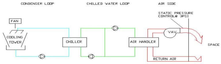
operate in the traditional manner. To do this, let us work back from
the liberation of the heat by the cooling tower to the occupied space
and define all of the control parameters from the cooling tower (or air
cooled condenser) to the space. A diagram of the full sequence is shown
below.
Working backward in the heat rejection process, from the tower to the space we have the following:
The cooling tower functions by passing water over the fill material, designed to create the greatest water and air contact, and into the tower basin. The tower fan will be operated to control water temperature in the basin to some desired level by forcing air to flow up through the tower. Even without the fan the hot water from the chiller will cause some level of convection airflow, due to the temperature differences. Not shown in the example drawing is the condenser water bypass valve that can divert water into the tower basin in cold weather and low load. Freeze protection is provided by tower basin heaters.
The condenser water pump operates the condenser water loop. The pump is selected to move the design quantity of water, gallon per minute, (GPM) through the condenser water barrel in the chiller. With safety factors the pump can be over sized.
The chiller compressor is sized to transfer the heat from the evaporator to the condenser. This compressor operational working range is usually defined over a narrow set of operating curves, specifying entering water and leaving water temperatures. Very cold condenser water generally limited to 10 degrees F above chilled water (verify requirements from the chiller manufacturer) can cause internal refrigerant flow problems for the compressor.
The evaporator water pump or pumps are designed to get the chilled water to the air handler. There are many possible configurations for the chilled water design. (See the chilled water design example.)
The air handler is designed to convey the airside heat to the chilled water, and to supply the cooled air to the space. There are many design variations here also. In this example we consider variable air volume (VAV) as the airside control. The air handler may use a variable frequency drive, inlet air dampers or outlet air dampers to vary the airflow. Typically the air handler controlled to provide a fixed pressure output to the ductwork. The operating pressure was established in the design analysis.
The airflow is conveyed to the VAV box, which based on the local sensor will cool as necessary to meet the temperature set point.
Each of the above system components function as an autonomous elements, controlled by individual set points. Let’s go back through my simple example and determine how many control loops exist:
Cooling tower
Condenser water
Pump with pressure verification generally on/off (1)
Chiller
Chilled water pump(s)
Air handler
VAV box
Recognizing this to be a simple system we have about 15 control loops
total. For those of pure heart we will only consider the loops marked
with a (1) as controlling energy.
Even in this simple example we have 13 loops that all have an impact on the energy consumption for the entire system. Further I submit that if the information available to the 13 individual control loops were available to all 13-control loops the decision-making would further reduce facility energy consumption.
Opportunity for Single-Loop Software Solutions to HVAC Systems
Let’s evaluate the opportunity for energy reduction in each of the
control loops discussed above. For simplicity the energy consumed for
each HVAC element will be considered on a per unit basis as a percent
of the chiller power (horse power). And the opportunity for energy
reduction will be estimated per element.
Two inter-related principles have been discussed above. The existing approach of multiple, Single-Loop control subsystems, where the loops are not working together has tremendous energy savings opportunity.
Aggregate savings from the Single-Loop can range from 15-40 percent of the chiller energy. Typical numbers are 15-20 percent. Secondly, shortcomings in the existing subsystems may be overcome by operating the system as a Single-Loop reset with data from each subsystem. In practice other sub-systems can cover some or all, of the shortfall from parts of the larger system.
Summary
The discussion above opens a new opportunity to reduce energy
consumption. When we decouple the ductwork from continuous temperature
flow and begin to think in terms of the High Occupancy Vehicle (HOV)
lanes on the highways, we can use the ductwork by time phasing
the
temperature and quality of the air and routing that air to the area
with special needs.
About the Author
Alan is owner and Principal Engineer for Stewart Engineering Services.
His prior work includes 14-year veteran of Honeywell Inc, where he
developed a wide variety of facility and process solutions for fortune
100 companies. He is a Honeywell President’s Club member and recipient
of the Johnson and Johnson Quality award. He served twenty-one years in
the U.S. Air Force in a variety of engineering and technical roles;
both in flight simulation systems and facility operation and design.
Alan has
published several technical articles. He is active in AEE, ASHRAE and
NSPE. Alan is a licensed engineer in four states. His bachelor of
electrical engineering degree is from Rutgers University and his
graduate studies in mechanical engineering were through the Air Force
Institute of Technology.
[an error occurred while processing this directive]
[Click Banner To Learn More]
[Home Page] [The Automator] [About] [Subscribe ] [Contact Us]