|
February 2019
AutomatedBuildings.com
|
[an error occurred while processing this directive]
(Click
Message to Learn More)
|

The Hardware
When
you show someone a Beaglebone or Raspberry Pi and tell them that it’s
possible to use the thing as a serious controller the reaction is
usually total disbelief. I know this because that’s what I do all the
time at work. The type of response I get can be divided into these two
basic categories:
- I Don’t know what you are talking about. What is a pie?
- OK fine, but who cares? You can’t use that thing; it doesn’t have
a plastic case.
I
just returned from AHR for our Open-Hardware
Open-Software session where we discussed this exact subject. It was
great to see a large amount of interest in this topic. The room was
packed with industry professionals as well as those who were just
curious. There was a major shortage of seating for an already large
room, with people standing or simply sitting on the floor. The amount
of engagement and interaction from the audience was also surprising and
greatly welcomed. Their reaction was more or less evenly divided
between:
- I know what you are talking about, and no you are totally wrong.
- I know what you are talking about, and yes you are totally right.
The
truth is both opinions have validity. The difference between success
and failure are what steps you take to make a particular device
suitable for real use. You can’t just take one of these development
boards, add a couple small pieces to it, toss it on a VAV box and call
it a day. There’s a lot more that goes into a production device that is
not apparent when looking at it, such as months and months of
development and redesign, followed by reliability and compliance
testing. What separates a serious device that you can trust to run your
central plant from something that is just a toy with a sophisticated
processor?
Controller
Baseboard
A
lot of it has to do with the form-factor; if it looks like a
controller, then it is a controller. What the Single Board
Computer or developer board is missing is a ruggedized baseboard
or carrier board with all necessary peripheral components
as well as heavy duty connectors that make it suitable for industrial
use. Half of the controller is essentially missing. These hobbyist SBCs
have a strong commonality with the half of a controller often referred
to as a System on Module (SOM). The SOM board is usually
smaller than the baseboard and contains the applications processor, clock crystals, external
RAM, flash memory, power management, and supporting passive devices.
These smaller PCB boards are always higher in cost per board-unit-area
due to the fact they are usually more than four layers, feature finer
trace width, to accommodate a greater number of high-speed signals. The
small board, which is essentially the brain of the device, must have
some way to connect signals to its body. On most SOMs, signals are
escaped to the baseboard by routing to edge, mezzanine,
or pin-type, header connectors. Each style of connector
comes with its own size, reliability, and cost impact. Take a look at
two board hardware concept used in Google’s Android
Things platform project. Google provides a selection of certified
SOMs, and then the entrepreneur-developer provides their own
baseboard hardware.
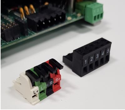
I/O and Connectors
The
most important part of an embedded edge controller is the physical
inputs and outputs. At the end of the day, having a complete personal
computer on a chip is totally useless unless it’s connected to interact
with the actual equipment we care about. Controllers attached to
equipment are typically equipped with at least five wired sensor
inputs.
To
receive these signals, we attach simple passive circuity to an Analog
to Digital Converter (ADC). Many embedded processors have on-chip
ADC modules with multiple input channels. A factory controller
uses ADCs as the basis for what is commonly referred to as the Universal
Input. If a greater number of inputs are needed, additional
external low-cost ADC chips can be added. Adding lots of inputs to a
controller is actually very easy. We will have to scale, filter, and
protect the incoming input signal before it is applied to the ADC. This
signal conditioning circuitry before the ADC input is often referred to
as an Analog Front End. When you set the input jumpers of a
typical building controller, you are connecting your signal to the
appropriate AFE circuit. Each selectable jumper position connects the
input to a voltage divider circuit that will give a suitable usable
scaled range.
For
example, a 4-20mA current transmitter signal passing through a 250-ohm
precision resistor will scale to an input voltage range of 1V - 5V on a
five volt ADC device. A pull up resistor connected to a voltage
reference can be used for the Thermistor and Dry Relay Contact type
inputs. Simple filtering circuits using resistors and capacitors are
normally placed to eliminate electrical noise from reaching the ADC.
For example, a 10K ohm resistor and the 1uF capacitor will form a
simple low pass filter that will reject any noise from frequencies
above 16Hz. The ADC module then returns a Count to the
controller software application which is a numerical representation of
the fraction of its maximum detectable voltage. The mapping of data
from ADC counts to physical values is a task accomplished in software.
If a particular sensor requires non-linear mapping such as a
thermistor, then curve fit functions, or lookup tables must be
implemented in the program.
It
was interesting to see at AHR in the controls area exhibits, the
increasing presence of board-component-level vendors showcasing the
exact items you find on production controllers. Companies who sell
circuit board components such as Sensirion and Metz-Connect were right there alongside vendors
with controls products that use their parts.
Network
Communications Ports
The
EIA-485/RS-485 standard forms the Physical
Layer for many building automation communication protocol schemes.
RS-485 provides an economical method to bring wired network
communication to multiple low-end devices that are only equipped with a
simple UART peripheral. Any device that has a UART
can easily implement an RS-485 network node. All that is needed is the
addition of an appropriate transceiver and supporting circuitry to
create a communicating network node. One of the main media types we
have relied on all of these years to connect most of the devices is BACnet
MSTP. The reason we have been stuck with MSTP for so long is
device cost. Most microcontrollers have plenty of UART modules.
Ethernet
and IP enabled controllers, however, require a much more sophisticated
peripheral know as Media Access Controller (MAC) and also
a physical layer chip often referred to as a Phy. In the
past, the MAC was usually a separate chip that had to be added to the
board and greatly added to the complexity and cost of a controller.
Therefore, IP connectivity was only found on gateways, routers, and
large plant-type controllers. These days there are least one or two MAC
modules on most SOCs, and they are fully integrated into the
applications processor itself. Not only that, many higher end
microcontrollers now commonly have built-in MACs. This particular trend
is one of the reasons we must start saying goodbye to our dear friend
MSTP. Walking the exhibit hall at AHR, I saw all of the new edge
controllers from different manufacturers being primarily IP based. Some
controllers had serial ports, but those were put there only to support
the addition of small secondary networks. The future controls network
topology will most likely be IP based. With this drastic change,
however, we now have the possibility of simplifying power installs by
using PoE.
Ruggedized Power
This
leads to another common criticism against using a single board computer
for building automation; that they do not accept 24VAC power using the
typical terminal block connectors. This is actually a simple thing to
fix. Designing a five-volt powered board to run on 24VAC power is an
extremely easy thing to do. 24VAC power is a standard voltage for
powering building automation system controllers.
Higher
DC voltages can be converted to lower ones through regulators.
Switching regulators are excellent for their power efficiency and are
useful in cases where the voltage delta between the regulated output
and unregulated input is large. Entire PCBs featuring adjustable
switching regulators can be found online for only a few dollars each
with all of the necessary components fully populated. These handy
boards are extremely useful for powering your embedded projects. The
only possible drawback to these types of regulators is the potential to
introduce switching noise. Switching regulators are not well suited for
directly supplying noise sensitive analog circuitry.
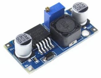
Complete
low-cost LM2596 switching regulator board for DIY projects
Linear
regulators are less noisy are the most efficient when the output
voltage is very near the unregulated input voltage. Of course, we must
ensure that the unregulated input does not go below the regulator’s
dropout voltage. Since these devices are usually half-wave rectified, a
reasonably large filtering capacitor will be required. Any filter
capacitor will have to charge quickly and provide the required current
during the negative cycle without dipping below the regulator’s dropout
voltage. Another important consideration is the lifespan of these
devices. Some types of capacitors lose capacitance over time.
Therefore, when considering the lifespan of the controller, a filter
capacitor should be slightly oversized.
Configuration
Switches
The
most important consideration in deploying large amounts of these edge
type devices is installation workflow. When commissioning
one or two devices, it is easy enough for the operator to manually
enter the initial settings such as a static IP address and other
equipment data. When this same task must be done for hundreds of
devices at once, the chore of initial setup becomes a lot more
cumbersome and time-consuming. At startup, each controller will be in a
default low-security initial unconfigured state. Each device needs some
type of unique identifier so that it can be found on the network
automatically and then receive the configuration data that was meant
for it. An important concept to keep in mind regarding the deployment
of these devices is that the person who ends up programming and
configuring the device is usually not the same person who physically
installs it. Not only that, these two activities are usually performed
at distinctly separate times. The addition of a few rotary encoders or
dip switches can be used to address and identify hundreds of devices.
This should be an adequate number for any particular network segment of
a building.
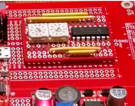
Rotary
decimal based encoders.
Isolation and Circuit Protection
Another
issue with using an SBC as a control device is the lack of protection
of the board edge I/O. In industrial environments, damage to the device
can occur from multiple sources. Damage to inputs can occur from things
as simple as the terminal blocks being incorrectly wired by the user to
surges caused by electrical disturbances and electrical fields. A
common way to protect these board edge terminal inputs is the use of
Varistors, Transient Diodes, and Fuses.
[an error occurred while processing this directive]We
can reduce the risk of damage to other components by adding the
following devices to edge connections:
Metal
Oxide Varistors (MOV) are good choices for protecting Universal
Inputs. If a voltage above say 30V is presented to an input, the
current is quickly directed to chassis ground. A good discussion
on MOV selection can be found here. In general through hole varistors are
capable of absorbing much more energy than surface mount devices.
Transient
Voltage Suppression (TVS) diodes. These are good for protecting
serial communication ports from short duration voltage overages that
are caused by electrical disturbances.
Fuses
are included where overcurrent is a possibility such as power inputs.
Fuses can also be added to the RS-485 port. Large induced currents are
a possibility from various electrical disturbances due to the long
transmission line lengths associated with the port.
Compliance
testing
Once
all of these items have been added to the board, you almost have your
own home-made controller. But don’t forget about compliance testing. In
the last part of this series next month we will discuss the final
piece; The Software. In the meantime, consider the
cautionary tale from the design development of this
PCB.
footer
[an error occurred while processing this directive]
[Click Banner To Learn More]
[Home Page] [The
Automator] [About] [Subscribe
] [Contact
Us]
 Calvin Slater